How To Read House Building Plans is a critical skill for many professionals, including architects, engineers, contractors, and homeowners. These plans are detailed drawings that provide a roadmap for constructing a house, ensuring that all aspects of the build are executed precisely as intended.
Knowing How To Read House Building Plans enables individuals to understand a house’s layout, dimensions, construction materials, and utility systems. This knowledge is essential for planning renovations, expansions, or general maintenance. Whether you’re a seasoned professional or a homeowner embarking on a building project, comprehending house building plans is key.
In this comprehensive article, we will delve into the intricacies of How To Read House Building Plans, breaking down the components and symbols used to convey essential information. We will explore different types of plans and how to interpret them effectively. Understanding these plans is a fundamental step towards successful construction projects and informed decision-making.
Reading house building plans effectively requires attention to specific key details. Here are ten crucial points to consider:
- Title block: General project information
- Scale: Proportion of drawing to actual size
- Dimensions: Length, width, and height of walls
- Symbols: Standardized representations of fixtures, materials, etc.
- Floor plan: Overhead view of each floor
- Elevations: Exterior views of each side of the house
- Sections: Vertical cuts through the house
- Details: Enlarged drawings of specific areas
- Schedules: Lists of materials, finishes, and fixtures
- Notes: Additional information and clarifications
Understanding these elements is essential for accurately interpreting house building plans and ensuring a successful construction project.
Title block: General project information
The title block of a house building plan is an essential component that provides a wealth of general project information. This information is crucial for understanding the scope, scale, and key details of the project. Typically located on the first page of the plan set, the title block includes the following essential elements:
Project title: This is a brief but descriptive name given to the project, which helps identify it and distinguish it from other projects. The project title is usually prominently displayed in the title block.
Project address: The project address specifies the location where the house will be built. This information is important for obtaining building permits, coordinating with contractors, and ensuring that the design complies with local building codes and zoning regulations.
Project number: Many architectural and engineering firms assign a unique project number to each project they undertake. This number serves as a reference identifier for the project and is used in all correspondence, drawings, and other project-related documents.
Date: The date on the title block indicates when the plan was created or last revised. This information is important for tracking the progress of the project and ensuring that the plans are up-to-date. It also helps identify any changes or modifications made to the plans over time.
Architect/engineer: The title block includes the name, contact information, and professional license number of the architect or engineer responsible for designing the house. This information is important for establishing the credibility and qualifications of the design professional.
Scale: The scale of the drawings is indicated in the title block. This information is crucial for understanding the proportional relationship between the drawings and the actual size of the house. It helps users accurately measure dimensions, calculate areas, and visualize the project’s overall size and layout.
By carefully reviewing and understanding the information contained in the title block, individuals can gain a clear understanding of the project’s scope, scale, and key details. This information is essential for effective communication, coordination, and decision-making throughout the construction process.
Scale: Proportion of drawing to actual size
The scale of a house building plan is a critical aspect that determines the proportional relationship between the drawings and the actual size of the house. It is typically indicated in the title block of the plan set and is expressed as a ratio or fraction.
Understanding the scale of the drawings is essential for accurately interpreting dimensions, calculating areas, and visualizing the overall size and layout of the house. Common scales used in house building plans include:
- 1/4 inch = 1 foot (1:48): This scale is commonly used for small to medium-sized houses and provides a relatively detailed representation of the design.
- 1/8 inch = 1 foot (1:96): This scale is often used for larger houses or complex projects and provides a more generalized overview of the design.
- 1/16 inch = 1 foot (1:192): This scale is typically used for site plans and shows the relationship between the house and its surrounding environment.
To use the scale effectively, individuals must pay attention to the units of measurement used on the plans. Most house building plans in the United States use imperial units (feet and inches), but some may use metric units (meters and centimeters). It is important to be aware of the units of measurement used to ensure accurate interpretation and calculations.
By understanding the scale of the drawings and the units of measurement used, individuals can accurately determine the dimensions of the house, calculate areas for materials ordering, and visualize the spatial relationships between different rooms and elements of the design. This information is crucial for effective planning, construction, and decision-making throughout the project.
In addition to the standard scales mentioned above, some plans may also include details drawn at a larger scale, such as 1/2 inch = 1 foot (1:24) or even full size (1:1). These larger-scale details provide more specific information about particular elements of the design, such as kitchen layouts, bathroom fixtures, or complex architectural features.
Overall, understanding the scale of house building plans is fundamental for accurately interpreting the drawings and making informed decisions during the design and construction process.
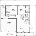
Dimensions: Length, width, and height of walls
Accurately understanding the dimensions of a house is crucial for planning, construction, and material estimation. House building plans clearly indicate the length, width, and height of walls, providing essential information for various aspects of the project.
- Overall dimensions:
The overall dimensions of a house refer to its length, width, and height from the foundation to the roof peak. These dimensions determine the overall size and footprint of the house on the building site and influence factors such as land requirements, materials needed, and construction costs.
- Exterior wall dimensions:
Exterior wall dimensions specify the length and height of each exterior wall of the house. This information is essential for calculating the amount of siding, insulation, and other exterior materials required. It also helps determine the placement of windows, doors, and other openings.
- Interior wall dimensions:
Interior wall dimensions specify the length and height of each interior wall within the house. This information is crucial for determining the layout and flow of the house, as well as the placement of doors, windows, and built-in features such as cabinets and shelves.
- Ceiling heights:
Ceiling heights indicate the vertical distance from the floor to the ceiling in each room. Different rooms may have varying ceiling heights, such as higher ceilings in living areas and lower ceilings in hallways or closets. Understanding ceiling heights is important for space planning, lighting design, and HVAC system calculations.
Overall, accurately interpreting the dimensions of a house building plan ensures that the constructed house meets the intended design and functional requirements. It enables precise material ordering, efficient construction practices, and a well-executed final product.
Symbols: Standardized representations of fixtures, materials, etc.
Symbols play a vital role in house building plans, providing a standardized and efficient way to represent fixtures, materials, and various elements of the design. These symbols are universally recognized and understood by architects, engineers, contractors, and other professionals involved in the construction industry.
Each symbol represents a specific element or component of the house, such as a window, door, plumbing fixture, or electrical outlet. By using symbols, architects and engineers can convey complex information in a concise and clear manner, avoiding the need for lengthy written descriptions.
Symbols are typically organized into different categories, such as architectural symbols, electrical symbols, plumbing symbols, and mechanical symbols. Each category has its own set of unique symbols that are designed to represent specific elements within that particular discipline.
For example, architectural symbols may include different types of walls, doors, windows, and stairs. Electrical symbols represent various electrical components, such as outlets, switches, and lighting fixtures. Plumbing symbols depict fixtures and fittings, such as sinks, toilets, and water heaters. Mechanical symbols represent HVAC systems, including ducts, vents, and equipment.
Understanding the standardized symbols used in house building plans is essential for effectively interpreting the drawings. By referencing symbol libraries or consulting with experienced professionals, individuals can accurately identify and understand the various elements represented in the plans.
Benefits of Using Symbols in House Building Plans:
- Enhanced clarity and precision: Symbols provide a clear and concise way to convey complex information, reducing the potential for misinterpretation or confusion.
- Universal understanding: Standardized symbols are universally recognized by professionals in the construction industry, facilitating effective communication and collaboration.
- Space optimization: Symbols allow for efficient use of space on the plans, enabling architects and engineers to convey maximum information within a limited area.
- Time-saving: Using symbols saves time and effort compared to writing out detailed descriptions for each element, increasing the efficiency of the design process.
- Consistency: Symbols ensure consistency in the representation of elements throughout the plans, reducing the risk of errors and omissions.
Overall, symbols are an essential aspect of house building plans, providing a standardized and effective means of communicating design information. Understanding these symbols is crucial for accurately interpreting the plans and ensuring a successful construction project.
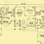
Floor plan: Overhead view of each floor
Floor plans are a fundamental component of house building plans, providing a detailed overhead view of each floor of the house. These plans depict the layout of rooms, walls, doors, windows, and other structural elements, allowing individuals to visualize the spatial relationships and flow of the house.
- Room layout:
Floor plans clearly show the layout and arrangement of rooms within each floor. This information is crucial for understanding the overall functionality and livability of the house. It helps determine the flow of traffic, the placement of furniture, and the adjacencies between different spaces.
- Wall placement and dimensions:
Floor plans indicate the location and dimensions of all walls within each floor. This information is essential for determining the size and shape of each room, as well as the placement of windows, doors, and other openings. Accurate wall dimensions are also necessary for calculating material quantities and ensuring structural integrity.
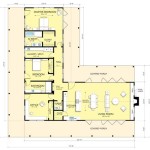
- Door and window placement:
Floor plans precisely show the location and size of all doors and windows in each room. This information is crucial for planning furniture placement, ensuring adequate natural light, and providing access to different areas of the house. Understanding door and window placement is also important for safety and accessibility considerations.
- Built-in features:
Floor plans often include details of built-in features, such as fireplaces, bookshelves, and cabinetry. These features are typically represented by specific symbols or notations on the plans. Understanding the placement and dimensions of built-in features is essential for space planning and interior design.
Overall, floor plans provide a comprehensive overview of each floor of the house, enabling individuals to visualize the layout, dimensions, and relationships between different spaces. This information is invaluable for architects, engineers, contractors, and homeowners alike, as it serves as the foundation for informed decision-making throughout the design and construction process.
Elevations: Exterior views of each side of the house
Elevations are a critical component of house building plans, providing exterior views of each side of the house. These drawings depict the overall form and appearance of the house, allowing individuals to visualize the exterior design, proportions, and relationship to the surrounding environment.
- Front elevation:
The front elevation shows the exterior view of the house from the front. It typically includes the main entrance, windows, doors, and other architectural features that define the front facade of the house.
- Rear elevation:
The rear elevation depicts the exterior view of the house from the back. It often includes elements such as patios, decks, garages, and other features that are typically located at the rear of the house.
- Side elevations:
Side elevations show the exterior views of the house from the left and right sides. These drawings provide information about the overall height, roof pitch, and other design elements that are visible from the sides of the house.
- Details and dimensions:
Elevations often include detailed drawings and dimensions that provide specific information about exterior materials, window and door sizes, and other architectural features. These details are essential for accurate construction and ensure that the exterior of the house is built according to the design intent.
Overall, elevations are essential for visualizing the exterior appearance of the house, understanding the relationship between different facades, and ensuring that the design intent is accurately conveyed to builders and contractors. These drawings play a vital role in the design and construction process, enabling informed decision-making and ensuring a successful outcome.
Sections: Vertical cuts through the house
Sections are detailed drawings that provide vertical cuts through the house, revealing the interior structure, spatial relationships, and construction details. These drawings are essential for understanding the three-dimensional aspects of the design and for coordinating the work of different trades during construction.
Sections are typically taken through critical areas of the house, such as the living room, kitchen, bathrooms, and bedrooms. They show the height of ceilings, the location of windows and doors, the placement of built-in features, and the relationship between different spaces. Sections also provide valuable information about the structural system of the house, including the foundation, framing, and roof structure.
In addition to providing a comprehensive view of the interior, sections also include detailed information about materials, finishes, and construction methods. This information is crucial for contractors to accurately build the house according to the design intent. Sections often include notes and specifications that provide additional guidance and ensure that the construction process is executed as intended.
Overall, sections are an essential component of house building plans, providing a wealth of information that is critical for understanding the design, coordinating construction, and ensuring a successful outcome.
Details: Enlarged drawings of specific areas
Details are enlarged drawings of specific areas of the house building plans that provide additional information and clarification beyond what is shown in the floor plans, elevations, and sections. These drawings are essential for understanding complex architectural features, construction methods, and material specifications.
Details are typically drawn at a larger scale than the rest of the plans, allowing for a more detailed representation of specific elements. They often include dimensions, notes, and symbols to provide precise instructions for construction. Details can cover a wide range of elements, including:
- Millwork: Details for millwork, such as moldings, trim, and cabinetry, provide specific profiles, dimensions, and materials.
- Built-in features: Details for built-in features, such as fireplaces, bookshelves, and seating, show the construction methods, dimensions, and material specifications.
- Stairways: Details for stairways include the dimensions, materials, and construction details of stairs, railings, and landings.
- Bathrooms: Details for bathrooms show the layout of fixtures, the location of plumbing connections, and the materials and finishes used.
- Kitchens: Details for kitchens include the layout of appliances, countertops, and cabinetry, as well as the location of electrical and plumbing connections.
Overall, details are an essential component of house building plans, providing the necessary information to accurately construct and finish the house according to the design intent. They serve as a valuable resource for contractors, builders, and homeowners alike, ensuring that all aspects of the construction process are executed with precision and care.
Schedules: Lists of materials, finishes, and fixtures
Schedules are comprehensive lists that provide detailed information about the materials, finishes, and fixtures used throughout the house. These schedules are essential for ensuring that all necessary materials are ordered and installed correctly during the construction process.
Schedules are typically organized into different categories, such as:
- Material schedule: Lists all of the materials used in the construction of the house, including lumber, concrete, roofing, siding, and insulation.
- Finish schedule: Lists all of the finishes used in the house, including paint, flooring, countertops, and hardware.
- Fixture schedule: Lists all of the fixtures used in the house, including appliances, plumbing fixtures, lighting fixtures, and door hardware.
Each schedule typically includes the following information:
- Item description: A brief description of the item, including the material, finish, or fixture type.
- Quantity: The number of units required for the project.
- Location: The specific location where the item will be installed.
- Supplier: The name and contact information of the supplier where the item can be purchased.
- Notes: Any additional information or specifications related to the item.
Schedules are an essential tool for contractors and builders, as they provide a comprehensive overview of all the materials, finishes, and fixtures that are required for the project. By carefully reviewing and understanding the schedules, contractors can ensure that they have all the necessary information to accurately estimate costs, order materials, and coordinate the installation process.
Notes: Additional information and clarifications
Notes are an essential part of house building plans, providing additional information and clarifications that may not be evident from the drawings alone. These notes can cover a wide range of topics, including:
- Construction details: Notes may provide specific instructions or details regarding construction methods, material specifications, or installation requirements. This information is crucial for ensuring that the house is built according to the design intent and meets all applicable building codes.
- Material specifications: Notes may specify the exact materials to be used for certain elements of the house, such as the type of wood for framing, the grade of concrete for the foundation, or the finish for the flooring. This information ensures that the materials used are appropriate for the intended purpose and meet the desired quality standards.
- Equipment and appliance specifications: Notes may provide details about the specific equipment and appliances to be installed in the house, including their make, model, and performance specifications. This information is important for ensuring that the equipment and appliances are compatible with the house’s electrical and plumbing systems and meet the homeowner’s needs.
- Codes and regulations: Notes may reference specific building codes or regulations that apply to the project. This information ensures that the house is designed and built in compliance with all applicable laws and standards, ensuring the safety and habitability of the structure.
Overall, notes are an invaluable resource for understanding the intricacies of house building plans and ensuring that the construction process proceeds smoothly and efficiently. By carefully reviewing and understanding the notes, individuals involved in the project can make informed decisions and ensure that the final product meets the desired design and functional requirements.


Related Posts